|
 |
DiscoverCircuits.com -- Hobby Corner
Last Updated on:
Tuesday, June 01, 2021 03:06 PM
Hobby Circuits List
The contents &
graphics of Discovercircuits.com are copyright protected.
LINK to Dave's circuit, but DO NOT COPY any files to your WEB
SITE server |
|
|
|
|
More
Motor Controller Circuits |
|
Motor Speed & Torque Limiting
Circuit
May 5, 2007 |
In many applications, you would like to hold the speed of a motor constant, even as
variations in the power supply voltage or mechanical load try to change its speed.
In other applications, the average current to the motor needs to be limited, so the
initial in-rush current when starting the motor is not too high. Also in some
applications you would like to allow the motor to be in locked in a stall condition,
without doing harm to the motor or the drive circuit. These two features can
often be combined in a single control circuit. |
|
|
|
There are many ways you
can monitor the speed of a DC motor. Some techniques connect some type of rotary
sensor directly the motor shaft. This method can often lead to a very accurate
speed measurement, since the sensor may produce multiple pulses per shaft rotation.
There are countless optical and magnetic sensors available for this purpose. When
possible, I like dispense with any external sensor and to tap into the signals produced
by the motor itself, to gage the motor speed. Motors with a three phase brush commutator
(three brush rings) will usually produce a very clean back emf signal.
|
|
|
This
is the voltage produced by the motor, if it was coasting at a specific speed,
without any applied drive. Knowing the relationship between the back emf
voltage and the shaft speed, you can design a circuit to maintain any constant motor
speed by monitoring the back emf voltage. But, few motors use a three phase
commutator. Most DC brush motors you will encounter will be single phase type.
Often these DC motors will produce clean current pulses, each time the brush
commutator changes the polarity of the DC applied to the motor windings. Using a
small resistance in series with the motor drive circuit, you can extract these
pulses to measure the motor speed. For many inexpensive motors, which are
often used in toys and some consumer appliances, neither the back emf method nor the
brush current pulse methods will work. The signals are just too noisy to be
practical. With these motors, only an external shaft sensor will work.
You will have to conduct some experiments on the particular motor you want to
control, to determine the best speed monitoring method. |
|
|
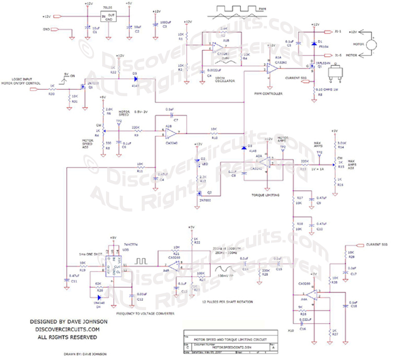
The circuit below is a
speed control for a medium power 12v DC operated single phase brush motor. It uses the
brush current pulse method to monitor the motor speed. It includes a method to
limit the average motor current. I have also included a means to turn on and off
the motor from a simple TTL logic signal. |
|
The circuit uses some
rather old op Amp ICs I had laying around. Other op Amps and voltage comparators could
also be used. The circuit uses a pulse width modulation (PWM) scheme to control
both the motor speed and the maximum average current. The current control is handy
when you want to limit the motor torque, since motor current and torque are directly
related. |
|
The circuit uses the
current pulses from the motor brushes to extract the motor speed. For the motor I used,
there were exactly 12 pulses per shaft rotation. The typical average motor current was
about 1.2 Amps with a speed of about 1000RPM. At 1000 RPM, the pulse frequency
works out to be 200Hz. |
A 10KHz ramp generating oscillator is
used as the timing generator for the PWM circuit. An op Amp compares the ramp
voltage with the control voltage from either the current limiting circuit or the speed
control circuit. When in current limit, the speed control part of the circuit is
pushed out of the way. A multi-pole low pass filter, removes the brush current
pulses from the motor, which appear across a small 0.1 ohm resistor. The pulses
are Amplified by a factor of X10 using A4. The signal from the pulse Amplifier is
then routed to a comparator circuit, which generates a square wave type signal.
That signal is then connected to a one-shot circuit, which uses one half of a dual
D-flip/flop IC. The output of the one shot is then filtered, to produce a voltage,
proportional to the pulse frequency. An op Amp then compares the speed signal to
an adjustable reference signal. The output of the speed error Amp, then is
connected to the PWM circuit, to maintain a constant motor speed. |
|
In a second circuit, the average DC
current is monitored using the DC voltage across the 0.1 ohm shunt resistor. It
too has an adjustable reference, so the limiting current (torque) can be controlled.
A diode isolates the two control circuits from the PWM circuit. A second diode
routes +5v to the PWM control input, when the on/off input logic control signal is low.
This pushes the PWM output signal low, keeping the motor turned off. A 5v voltage
regulator is used to provide a stable +5v voltage to the speed and torque reference
circuits. |
|
|
Click on Circuit Below to view PDF of Schematic |
|
 |
|
|
|
More
Motor Controller Circuits
Hobby Circuits List
eMail David A.
Johnson, P.E. about this circuit |